History of Astrodevice filter drawers
In 2022, I developed the first filter drawers for ZWO ASI 2400, 2600, 6200, and 071 cameras and Celestron RASA 8 telescopes. The FD 900 M87 and FD 860 M87 – as they were designated – solved the problem of short backfocus: a camera with a native backfocus of 17.5 mm and a telescope requiring a sensor at a distance of 28.73 mm from the mounting plane gave a total of just over 11 mm for the entire drawer. Fittin g the entire mechanism into such a narrow space seemed like quite a challenge. I solved this problem by removing the tilt plate from the camera, which gave me an extra 5 mm of space. This resulted in a drawer that was screwed directly to the camera, replacing the factory tilt plate and meeting the very strict requirements of the fast optics of the Celestron RASA 8 telescope.
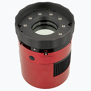
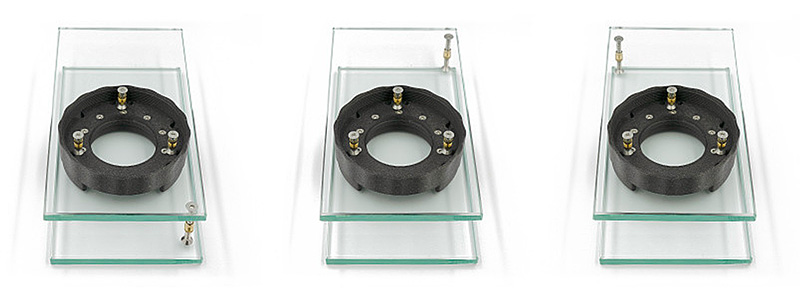
To design a drawer for this telescope, it was not enough to focus on the form alone. Combining a camera with a large sensor with such fast telescope optics requires extraordinary precision. Therefore, the drawer was equipped with a special calibration system that allowed for very precise adjustment of the parallelism of its mounting planes. This was a necessary requirement for a device whose parts were 3D printed. After assembling the whole thing using calibration, it was essential to remove all the irregularities that arose at the junction of the separately manufactured components. In addition, there was a purely technological problem with 3D printing using filament: the U-shaped part of the drawer, which was adjacent to the bed during printing, shrunk disproportionately as the temperature dropped after printing: faster and more strongly in areas with low curvature (where the filter slider enters), and slower at the back, where the curvature is greater. The combination of the temperature gradient between the constantly hot table and the gradually cooling filament with varying heat dissipation geometry, after printing, resulted in a significant difference in thickness in these areas, reaching up to a few tenths of a millimeter. This, in turn, led to tilt, which had to be compensated for with a sophisticated system of calibration screws. Ultimately, the whole thing worked perfectly, but its complex design and the need for precise initial calibration ruled out the possibility of DIY construction.
For this reason, the drawer was only offered commercially as a complex, ready-made product. At the same time, variants of drawers with a 42 mm external thread and other designs to improve astrophotography work were developed.
Over time, I focused on other conceptual projects, concentrating on engineering challenges while limiting my business involvement to presenting short series. In 2024, I ended the sale of my solutions, although—as a designer—I remained active in the field of device design for astronomy and astrophotography. At the same time, I kept thinking about how to redesign the drawers to make widespread, independent 3D printing possible.
Finally, I managed to create a form that met all these requirements. I designed a uniform filter drawer core that can be printed in one piece and, thanks to its rather “twisted” geometry, can be fitted with a nut collar that is generally narrower than it. This made it possible for anyone with a 3D printer to make the design themselves.
By applying a new geometry and, as a result, changing the orientation of the drawer core print, I eliminated the need for calibration screws. Admittedly, the screws allowed for an accuracy more than ten times greater than the average accuracy of 3D printing, but in the case of the simplified version of the drawer, I came to the conclusion that ease of manufacture and widespread availability are the overriding goals. With proper printing, using an efficient, well-calibrated printer and dry filament, a precision of the printing process should be sufficient to achieve a very satisfactory result.
Of course, it should be borne in mind that since the original commercial drawer had perfectly parallel planes with an accuracy of thousandths of a millimeter, the new monoblock version without a calibration system will, by definition, be less accurate. However, there is a trade-off: the ease and fun of making the new version yourself, the minimal cost, and the very good results that can be achieved may be advantages for many people, making it worthwhile to make your own filter drawer.

Compared to the original design, not only are calibration screws no longer present, but I have also dispensed with tilt adjustment screws. The main factor introducing tilt into the optical path are the elements connecting the telescope to the camera. If the telescope and camera are in good operating condition and the drawer connecting them has truly parallel planes that perfectly fit the mounting planes of the camera and telescope, there should be no need for additional adjustment. Astrodevice drawers have been successfully used with full-frame cameras and no significant image distortion has been reported. Introducing additional degrees of freedom by using additional tilt adjustment screws usually only made the work more difficult instead of easier. I have described the issue of tilt in a separate article, so if you would like to learn more about the problem, I invite you to read it.