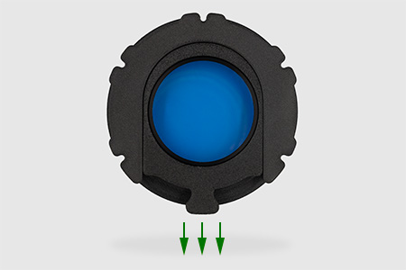
for RASA 8 and ZWO ASI or Player One cameras with 17.5 mm backfocus
Here, I describe how to make a filter drawer for connecting Celestron RASA 8 telescopes and ZWO ASI or Player One cameras with a backfocus of 17.5 mm. The design is intended for DIY 3D printing and it is a simplified version of the previous commercial drawer, which has proven itself in astrophotography.
MB-FD 860 M87 drawer for cameras having 86 mm diameter:
ZWO ASI 071 MC Pro
The only two elements that differ between the two versions for ZWO is the drawer core and side blinder. So choose the one that is designed for your camera for printing.
The drawer for Player One cameras is available in one variant:
MB-FD P1 M87 drawer for the following cameras:
Player One Zeus 455 M/C Pro
Player One Poseidon M/C Pro
Player One Artemis M/C Pro
The Player One version differs very slightly from ZWO in the core geometry and M87 nut cutouts. The other components (sliders, key, and side blinder) are identical.
About the version for Player One cameras:
The variant for Player One cameras was created as an adaptation of the previously released version for ZWO cameras. Since I do not have a Player One camera in my collection, I asked the manufacturer, Player One Astronomy, for help and asked them to send me a physical Zeus camera housing. Thanks to their fantastic support and assistance, this way I was able to precisely adapt my drawer to Player One cameras.
However, please note that I have not yet personally taken any photographs with Player One cameras and the adapted version of the Astrodevice drawer. I only have the housing and not a fully functional camera. Therefore, until I receive sufficient confirmation from people who have tested my new solution themselves, the Player One version should formally be considered a beta version. If you have made the drawer and tested it with a Player One camera, please let me know if everything works as well as I expect it to.
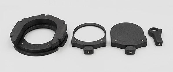
The entire device consists of six standard components:
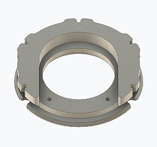
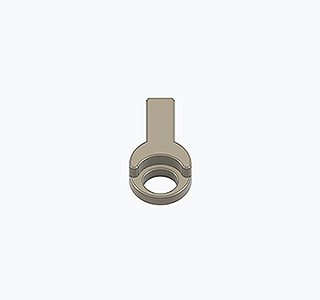
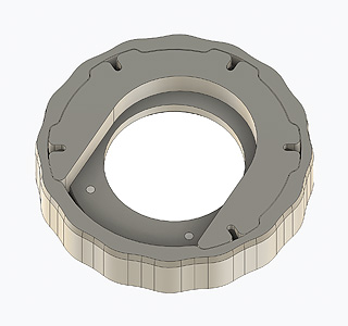
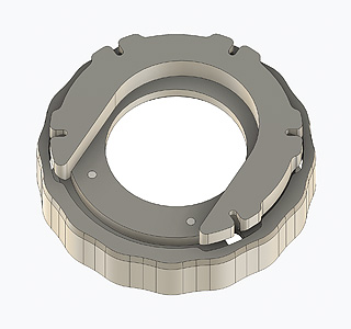
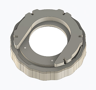
Core of the drawer
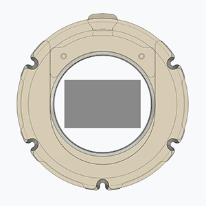
The main part of the device into which the filter slider is inserted. The core comes in two versions (900 and 860).
2" filter slider
Holds a standard 2” threaded filter
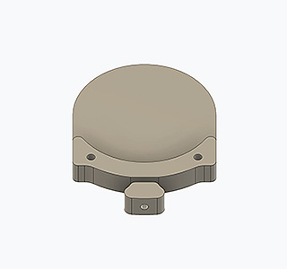
Blind slider
Used to make dark and bias frames
M87 nut
Used to attach the drawer to the RASA 8 telescope.
Magnetic key
It helps to easily pull out the slider from the drawer.
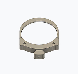
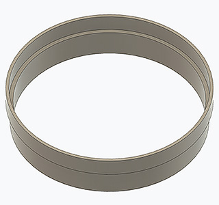
Side blinder
Protects the drawer from false light that may enter the sensor from the side. The blinder comes in two versions (900 and 860).
Fig.1 - Core of the drawer
Fig.2 - 2 inch filter slider
Fig.3 - Blind slider
Fig.4 - M87 nut
Fig.5 - Magnetic key
Fig.6 - Side blinder
The illustrations above show the shape of the core of the drawer and the M87 nut from the packages intended for ZWO cameras. The shapes of these components for Player One cameras differ only minimally. The difference is not significant enough to be necessary to include separate drawings here. The relevance of the components and the way they are arranged on the bed during printing is the same as described above.
The components should be printed in the orientation shown in the above drawings, without using any supports. The core and magnetic key should have a layer height of 0.2 mm, while the M98 nut and sliders should have a layer height of 0.1 mm, except for the first layer, which should be 0.2 mm. Of course, everything need to be made from well-dried PETG+CF filament.
General information on preparing for printing, the printing process, and its completion, including information on the required filament, printing speeds, and other technical parameters, is provided in a separate article. Before you continue, make sure you have read it and understood all the information it contains. Only by following all the instructions there will you be able to be sure that the device will work properly.
At this point, however, I would like to draw attention to one very important printing parameter: the cooling fan. In these prints, dimensional accuracy is critically important. The drawer core is a particularly essential component here. Its upper and lower surfaces must be perfectly parallel, otherwise tilt will occur. The problem is that the geometry of this U-shaped element has two small-radius curvatures, located at the entrance to the filter slider slot. There, the shrinkage of the filament during cooling while printing is diametrically different from the rest of the drawer. If we printed this element from pure PETG with low cooling airflow, the thickness of the drawer in this area would be significantly less than, for example, in its rear part. The difference could be as much as 0.5 mm or more. This would cause dramatic tilt. The use of carbon fiber additive improves the result, but in order to really cope with the different shrinkage dynamics, the cooling fan speed should be set to 100%. I want to draw particular attention to this – from the third layer upwards, print the core of the drawer with 100% cooling. Only this, in combination with a good filament, will allow you to print truly parallel planes.
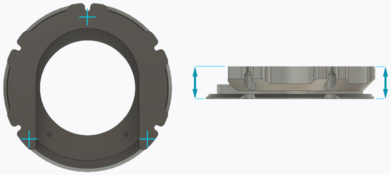
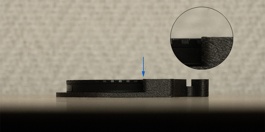
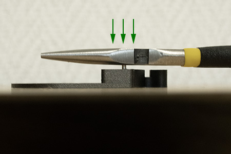
To make sure that the print has come out correctly, after it is finished, allow the elements to cool on the print bed and only then remove them from it. After printing, check that there is no layer separation or other printing errors due to the strong cooling. Then measure the core dimensions of the drawer in three places with a caliper, as shown in the figure below. The thickness at all three points should be the same and equal to 16.2 mm.
Fig.6 - Top and side view of the drawer core. Three points are marked where the thickness of the core should be measured after printing.
Theoretically, the drawer is ready for use immediately after printing. It would be enough to assemble it and attach it to the camera and telescope. However, this would cause a number of problems: first, after unscrewing the tilt plate, we only have three original mounting screws, which are not suitable due to the shape of their heads. Secondly, the slider could easily fall out of the drawer when changing the filter because there is no force to hold it inside. Thirdly, minor imperfections in the print could cause unexpected tilt.
Therefore, to complete the drawer, it is worth purchasing a few additional materials and taking a moment to properly finish the freshly printed parts. This process will significantly increase the comfort and safety of using the filter drawer. The cost of these additional parts should not exceed a few dollars.
The drawer can be fitted with magnets that will hold the filter slider inside. This will eliminate the risk of the slider with the filter falling out when it is removed, which could result in the valuable filter being broken. It will be much better if, after applying the magnets, the slider is secured against unwanted sliding out.
The slider can be fitted with a magnet in the handle, which makes it much easier to slide out. Simply attach a second magnet to the special key that comes with the set, and sliding out the drawer will be extremely easy, even in complete darkness.
The drawer can be attached to the camera with as many as 5 screws, which significantly increases the security of the mounting, compared to the option of using only three original screws from the black tilt plate. At the same time, these 5 new screws, thanks to their conical heads, attach the drawer to the camera much more securely. In addition, a larger number of mounting points gives much greater certainty of maintaining an even contact surface and, as a result, reduces the possibility of unwanted tilt.
Bill of materials needed to make a complete version of the filter drawer:
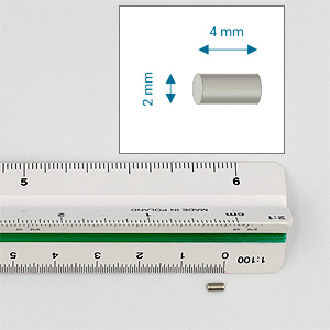
2x4 mm cylindrical neodymium magnets (Φ 2 mm, L=4 mm)
2 pcs for core,
2 pcs for each slider (2" and blind)
For example, let's assume that you want to have each filter already screwed into the drawer so that you can easily change it during work without having to unscrew the old one and screw in the new one each time. You have 7 filters (L, R, G, B, S, H, O), so you need to print 7 sliders. In this case, you need a total of 16 magnets: 2 for the core and 14 for the sliders.
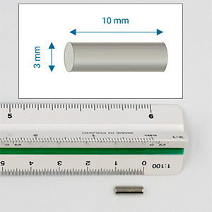
3x6 mm cylindrical neodymium magnets (Φ 3 mm, L=6 mm)
1 pcs for each slider (2" or blind)
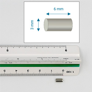
3x10 mm cylindrical neodymium magnets (Φ 3 mm, L=10 mm)
1 pcs for magnetic key
Screws:
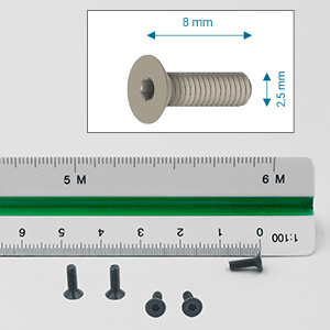
For ZWO: M2.5x8 countersunk (flat head) screws (Φ 2.5 mm, L=10 mm, metric thread, DIN 7991)
5 pcs to attach the core of the filter drawer to the camera
For Player One: M2.5x12 countersunk (flat head) screws (Φ 2.5 mm, L=12 mm, metric thread, DIN 7991)
6 pcs to attach the core of the filter drawer to the camera
The two most popular types of screws available on the market are Allen screws and Phillips screws. Allen screws have a very small socket (only 1.5 mm wide) and, when tightened too much, it can become worn, making it impossible to unscrew the screw.
If you have a choice, it is probably better to buy Phillips screws, whose sockets are much more resistant to wear in this case.
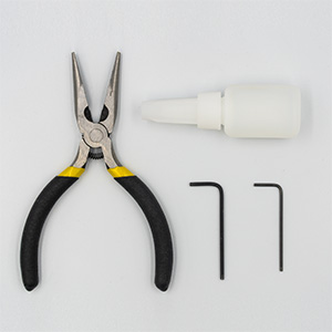
You will also need a few tools: pliers, Allen keys (2.0 mm for the camera and 1.5 mm for the additional five M2.5x8 screws, unless you have screws that require a Phillips screwdriver), 500 grit sandpaper and a tube of cyanoacrylate adhesive (e.g., superglue).
Fig.7 - Magnet 2x4 mm
Fig.8 - Magnet 2x6 mm
Fig.9 - Magnet 3x10 mm
Fig.10 - Screws M2.5x8 mm
Fig.11 - Drills Φ2 mm and Φ3 mm
Fig.12 - Tools: pliers, Allen keys, cyanoacrylate glue
For Player One you need M2.5x12 flathead screws, which are identical in shape to M2.5x8 in fig. 10, except that they are 12 mm long instead of 8 mm. Since these are screws of exactly the same type, for the sake of clarity, I am not adding a separate drawing for M2.5x12 here.
Before proceeding, read all instructions below carefully, ensure you understand them, and gather all necessary tools and parts.
After printing, check that everything went well and that there are no folds, blobs, zits, or other printing errors. The surfaces should be smooth, even, and free of any minor imperfections before further assembly.
Place a sheet of 500-grit sandpaper on the table. Place the drawer core on it, with the surface where the print ended facing down. The thing is, the upper surface of the print usually has some imperfections, such as local filament thickening. These can cause unwanted tilt. You can try to get rid of them by using the so-called ironing of the last layer in the slicer, but in this case this is not enough. The only sure way to level this surface is to sand it with very fine sandpaper.
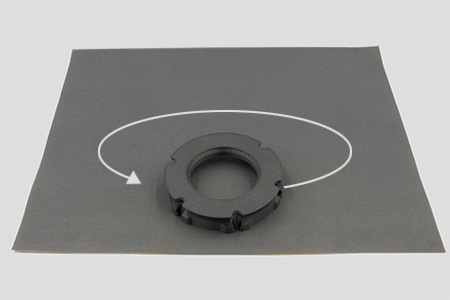
Once you have placed the drawer core on the sandpaper, grasp it evenly with your whole hand so that your fingers are evenly spaced around the circumference. Now make circular movements, moving the core across the sandpaper. Apply a little pressure, but not too much, directing the force centrally down. Try not to put too much weight on one edge, but direct the pressure perpendicularly downwards, applying even pressure to the entire core. After a few rotations, check the result. The surface should be evenly sanded. If you still see areas that have not been sanded, rotate the core 180 degrees and perform a few more rotational rubs. Continue rotating the core and rubbing it on the paper until the entire surface looks uniformly cleaned. Usually, 10-15 rotations should be enough to smooth the surface. Finally, sweep your hand over the sanded surface and check that it is completely smooth. Finally, wipe off any excess dust with a cloth.
Fig.13 - Sanding the drawer core
Screw the filter into the filter slider. If you followed the printing instructions, the filter should screw in smoothly. However, keep in mind that after printing, the surface of the fine thread may be slightly rough and require several turns of the filter in and out to become smooth. Never use force to screw in the filter. Place the filter on the filter slider and gently begin to screw it in. If the thread does not want to “catch,” first turn the filter lying on the slider a quarter turn counterclockwise to “settle” it in the mounting position. Then start screwing it in. If you encounter resistance while screwing, unscrew the filter and start screwing again. The first or second full screw-in of the filter may require several attempts. As a result, the filter should screw in freely to the end so that its upper surface does not protrude above the height of the filter slider.
Fig.13 - The filter should be screwed in completely so that it does not protrude above the upper surface of the slider
Screw the M87 nut onto the telescope thread and then unscrew it.
This step is to check that the print has been made correctly and that the thread fits well with the telescope and the nut reaches the end, being able to press down on the filter drawer.
Install the magnets in the filter slider.
The holes for the magnets have a small curvature, so they usually print slightly shrunk. Therefore, it may be necessary to gently widen them in order to insert the magnet. To achieve the perfect hole diameter, grasp the Φ 2 mm drill bit in a pair of pliers and try to screw it into the hole. By turning the drill bit, you need to reach the bottom of the hole and then pull the drill bit out while still turning it. Do not use a drill or cordless screwdriver for this, as you will easily drill through the print and destroy it. Only turning the drill bit by hand in the hole guarantees that you know what you are doing. After removing the drill bit, you can repeat the operation to be sure of the result and then blow out any remaining filings from inside the holes. If something remains inside, you will not be able to insert the magnet all the way, and if the magnet gets stuck, you will have to print the slider again.
Fig.14 - Precise enlargement of holes using a drill bit
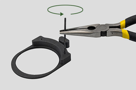
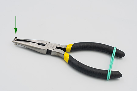
Before you start mounting magnets in printed parts, grab a 3x10 magnet with pliers and mark one of the poles with a colored marker (in the photo below, the top of the magnet is marked in black). In the rest of the text, we will refer to the poles of this auxiliary magnet as the “marked pole” and the “unmarked pole.”. Note, that this is the same magnet that you will eventually install in the magnetic key. For now, it will serve as an assistant magnet for installing other magnets in the printed components. For convenience, secure the pliers handles with a rubber band – this will significantly reduce the risk of the assistant magnet falling out during installation.
Fig.15 - Helpful tool for mounting magnets in printed components
After enlarging the holes, you have to insert the magnets: 2x4 at the top of the slider and 3x6 at the front of the handle. To do this, attach the magnet to the unmarked pole of the auxiliary magnet, which is held in the pliers.
Fig.16 - The method of positioning the mounted magnet in a determined pole orientation
Now place a drop of cyanoacrylate glue at the end of the magnet you are inserting into the hole. Simply touch the surface of the magnet to the narrow opening of the glue tube, and a drop will form itself on the magnet. If (as is very likely) a drop that is too large forms, gently touch the excess glue with a tissue. Remember not to squeeze the glue out of the tube onto the magnet, because you will flood it. This is a delicate operation, and to apply the glue, it is enough to slightly moisten the tip of the tube before contacting the magnet: the surface of the magnet will draw the glue onto itself upon contact.
Fig.17 - A small amount of cyanoacrylate adhesive on the tip of the magnet
Insert the magnet into the hole, with the adhesive side facing inward. Do not push it all the way in yet, but press the magnet in enough so that it does not fall out when you remove the pliers with the auxiliary magnet.
Fig.18 - Inserting a magnet into a hole while maintaining the correct polarity
Move the auxiliary magnet away and check that the painted surface has not been rubbed off. If so, repaint it and then remove the auxiliary magnet from the pliers, taking care not to rub off the markings again.
Next, push the mounted magnet with the flat hard part of the pliers. Make sure that after pushing it in, it does not protrude above the surface of the slider.
The holes in the printed elements are slightly deeper than the length of the magnets that will be inserted into them. The longer the magnet to be inserted, the greater the difference in hole depth. The point is that when a magnet is inserted into a tight hole, the air inside it is compressed. The longer the magnet, the more air has to be compressed. Therefore, push the magnets with a flat surface so that you can stop pushing when you align with the surface of the print. Pushing the magnet with a pointed tool (e.g., a screwdriver or the tip of pliers) may cause the magnet to be inserted too deeply.
Fig.19 - Push the magnet with a hard, flat surface, e.g., using the metal part of the pliers
Repeat the procedure for the second hole on the top surface of the slider in the same way, keeping the same side to which the auxiliary magnet is facing. This is critically important because we want both magnets to have the same pole orientation.
Finally, install the 3x6 magnet in the drawer handle in exactly the same way. Of course, in this case, you will need to use a Φ 3 mm drill bit to enlarge the hole. Again, maintain the same polarity as for the smaller magnets (i.e., attach the installed magnet to the unmarked pole of the auxiliary magnet).
And once again, as a reminder: immediately after installing each magnet in the hole, check that the color of the previously selected surface of the auxiliary magnet has not rubbed off (which is very likely when using a marker). If so, simply repaint the surface. If you cannot tell which side was painted, simply place the auxiliary magnet on the first installed magnet (on the upper surface of the filter slider). The selected surface of the auxiliary magnet is then its upper surface.
Install the magnets in the drawer core.
As with the filter slider, enlarge the holes with an Φ 2 mm drill bit and then insert the 2x4 magnets. Now you need to insert them with the opposite pole to the previous one facing inwards. So, in this case, attach the installed magnets to the MARKED POLE of the auxiliary magnet (opposite to the slider).
After installing the magnets, check that the slider slides into the drawer core and that the magnets hold it in place.
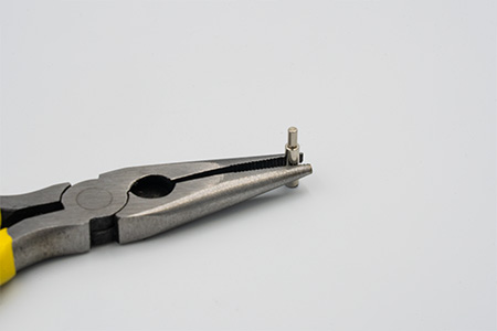
Install the magnet in the magnetic key.
In the same way as before, enlarge the keyhole with an Φ 3 mm drill bit and then insert the 3x10 magnet into it. The magnet to insert is just your auxiliary magnet with the marked pole facing inward. Here, too, you can use glue to ensure that the magnet does not slip out under the force of attraction from the other magnet.
At this point you should now have all the magnets installed.
Fig.20 - All printed parts with magnets installed
To summarize:
Sliders: attach magnets to the UNMARKED pole of the auxiliary magnet and insert them into holes.
Core: attach magnets to the MARKED pole of the auxiliary magnet and insert them into holes.
Magnetic key: insert your auxiliary magnet into hole so that its MARKED pole goes inward and UNMARKED faces outside.
Now conduct a test: screw the filter into the slider, insert the slider into the drawer, and carefully position it vertically to check that the slider with the filter does not fall out. If you have done everything correctly, the magnets should hold everything together and the slider should not slide out. During this experiment, secure the slider with your hand to ensure that it indeed does not fall out of the drawer and the filter will not be damaged.
Fig.21 - Gravity test of the slider after installing magnets
Slide the nut onto the drawer core.
The drawer core has appropriate indentations on its edge and the nut has matching notches. Both parts can only be assembled in one position. Slide the nut onto the drawer core and then turn it so that it does not slip off during further assembly.
Fig.22 - Match the nut against the core
Fig.23 - Slide the nut onto the core
Fig.24 - Turn the nut to prevent it from coming off
And that's it! Here's a checklist of what you should have already done:
You have printed all the parts in 3D and checked them: the print went perfectly.
The filter can be screwed into the filter slider (to the end of the thread), and the filter does not protrude above the upper surface of the slider.
You can screw the M87 nut onto the telescope.
You have placed the M87 nut on the drawers core.
If you are making the full version of the drawer, you have installed all the magnets and the poles are correctly oriented. You can slide the filter slider in and out of the drawer both manually and with a magnetic key, and once inserted, the filter slider sticks to the core of the drawer with the force of the magnets.
So the drawer is ready. Now you can install it on your camera and then screw it on the telescoope.
The installation procedure requires screwing the drawer to the camera. Due to the complex geometry of the drawer, screwing in the screws requires precision and attention. In particular, you should take care to screw the screws in straight, perpendicular to the plane in which the mounting hole is located. If the screw is screwed in crookedly, you are likely to damage the thread in the camera.
Therefore, always check that the screw is screwed in evenly and straight, perpendicular to the mounting hole surface.
Be gentle, screw in the screws slowly and carefully. The screws should screw in freely and easily. If you encounter any resistance, remove the screw immediately and, if necessary, remove the drawer and try to screw the screw into the hole by hand first, just for test, feeling whether it is going in correctly.
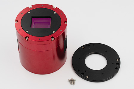
Place the camera on a flat table with the tilt plate facing up.
Using 2 mm Allen key, remove the three screws holding the tilt plate.
Take off the tilt plate.
Fig.25 - Camera with tilt plate removed
Place the filter drawer on the camera so that the slider entrance is on the long axis of the sensor. If the drawer causes any residual tilt correlated with the asymmetry of its U-shape, this tilt will most likely run along the axis on which the filter is inserted. Since the blurring of stars caused by tilt is more noticeable the further away from the center of the frame, we want the physical frame to end as close to the center as possible in the selected direction. Therefore, it is good to have the shorter side of the sensor on this axis.
Fig.25 - Suggested position of the drawer relative to the sensor
Secure the drawer to the camera with five M2.5x8 cone screws.
Tighten the screws gently, alternating between them. Tighten each screw a little at a time so that the drawer is pressed down evenly. Never use excessive force to avoid damaging the drawer and the thread in the camera housing.
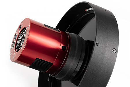
Fig.26 - Camera with a drawer installed
After screwing it in, carefully inspect the entire visible edge where the drawer adheres to the camera. The adhesion should be perfect everywhere. If the drawer sticks out even slightly anywhere, you need to find the cause: either you used a screw that is too long, or you did not tighten one of the screws completely, or there is a small particle between the camera and the drawer preventing it from pressing down completely, or something else is blocking the pressure. You need to find the cause, because uneven alignment will cause tilt. If you see uneven contact and the screws cannot be tightened further easily, do not try to force them, as you may damage the thread in the camera housing. A properly performed installation should have a perfect fit with reasonably tight screws. A good fit certainly does not require excessive force when tightening the screws.
The camera with the drawer attached is now ready to be mounted on the telescope.
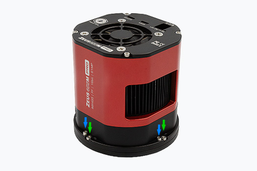
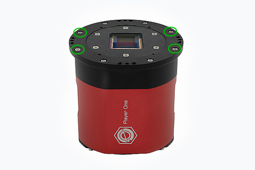
Place the camera on a flat table with the tilt plate facing down.
On each of the four sides of the camera, there is a pair of screws: one screw in each pair tightens the tilt plate (marked in green in the figure below) and the other adjusts the tilt (blue).
Fig.27 - Remove all 4 tilt plate mounting screws (green) and 4 tilt adjustment screws (blue)
Using a 2mm Allen key, remove all these screws - two on each side of the camera, 8 screws in total (4 “blue” and 4 “green”). Put these screws in a safe place right away, e.g., in a zip-lock bag, so that they don't get lost.
Take off the tilt plate.
Fig.28 - Camera with tilt plate removed
Remove two short structural screws:
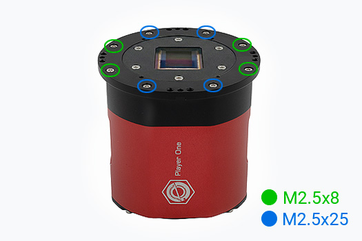
Get familiar with the camera's design:
The camera is structurally fastened with eight screws. These screws come in two different sizes: M2.5x8 (8 mm thread length) and M2.5x25 (25 mm thread length).
Fig.29 - Structural screws fastening the camera
Remove four SHORTER screws, M2.5x8, located on opposite sides of the housing with ventilation slots.
Fig.30 - Remove these four M2.5x8 screws from the housing
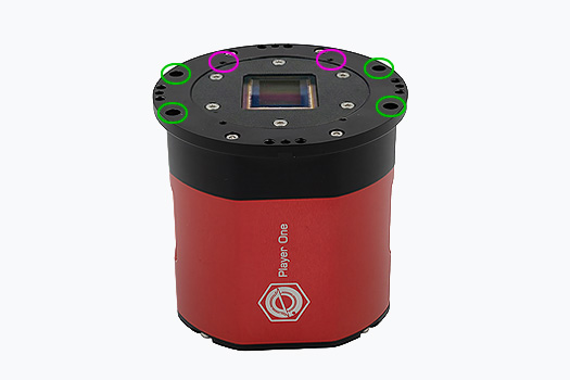
Screw the filter drawer in place:
Look at the fig. 31 below. There are six holes marked on it, which you will use to install the filter drawer. Four of them, marked in green, are the ones from which you just removed the screws. The two marked in purple are additional holes that you will use, and you should start the installation from them.
Fig.31 - Holes for mounting the filter drawer
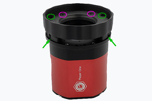
Place the filter drawer with the M87 nut attached on the upper surface of the camera. The hole into which the filter slider is inserted should be on the side of the camera with the Player One logo.
Fig.32 - Procedure for screwing in the filter drawer
Screw the drawer in place using the six M2.5x12 screws you purchased. First, screw two screws into the holes marked in purple. This will stabilize the drawer in the correct position and make it easier to screw in the remaining screws. Once the drawer is screwed in with these two screws, screw in the next four M2.5x12 screws in the places marked in green.
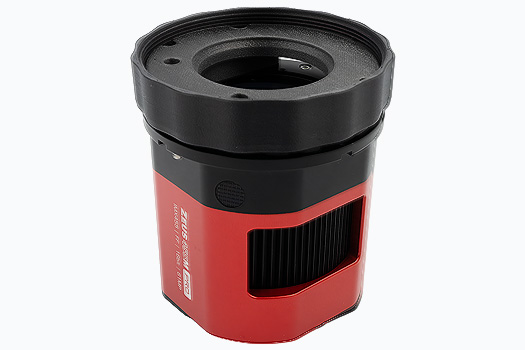
Fig.33 - Installed filter drawer
The camera with the drawer attached is now ready to be mounted on the telescope.
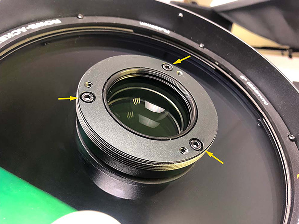
Remove the glass window from the front of the telescope.
The glass window affects the effective optical path length and it must not be used together with other filters. Also make sure all screws visible in the front metal plane of the telescope stays back, that they do not protrude forward the surface (see yellow arrows on the photo below).
The surface of the front mounting plane on the telescope should be smooth, even, and free of protrusions.
Fig.34 - Unscrew the glass cover of the corrector lens; the front surface should be smooth and free of protruding screws
Screw the camera with the mounted drawer onto the telescope.
Tighten it to the first stop, but do not force it. Tightening too much will compress the material, change the spatial shape of the optical path and adversely affect the image quality. The camera should be tightened without any play, as far as it will go, but in such a way that it can still be rotated with a quite low force. So: tight, but not overtight.
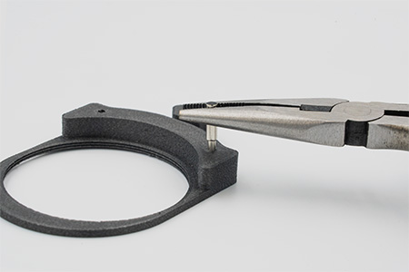
Insert the filter slider into the core of the drawer.
Screw the filter into the slider as you did the first time when you tested the printout. Then slide the slider into the drawer. Due to the small amount of space, it may be difficult to get the slider out with bare hands. With the help of a magnetic key, however, you can easily deal with this. Just put the key against the protruding part of the drawer and pull outward. Alternatively, you can use a hex key. Insert it into the specially designed cut-out and pull the slider out of the drawer.
Put on the band that protects the sensor from sidelight.
When taking pictures, the band should cover the filter drawer. To remove the filter slider, slide the band back.
Fig.22 - Telescope with M87 filder drawer, without side blinder
"
Fig.23 - Telescope with M87 filder drawer, with side blinder on
That is all! You are now ready to take pictures.
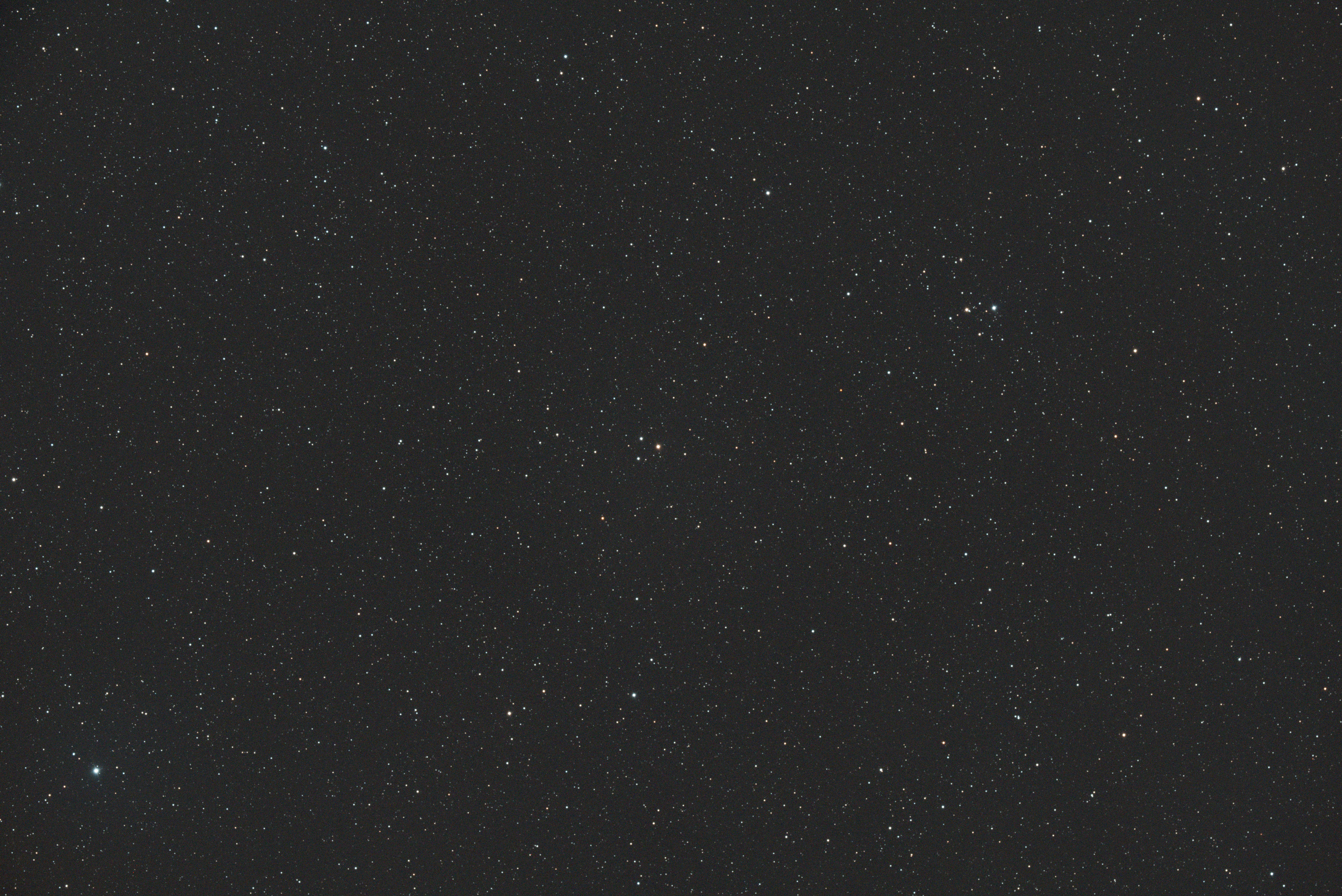
Here is the result obtained using the drawer made in this article, the ZWO ASI 2600 MC camera, and the IDAS NBZ filter. The first photo shows the entire image of a single, raw, uncalibrated frame. The following images show a 100% close-up of the selected regions of the resulting frame.
Fig.35 - A single frame taken with a color camera, IDAS NBZ filter, and a self-made M87 filter drawer.
Fig.36 - Upper-left corner of the image
Fig.37 - Upper-middle part of the image
Fig.38 - Upper-right corner of the image
Fig.39 - Center-left part of the image
Fig.40 - Center part of the image
Fig.41 - Center-right part of the image
Fig.42 - Lower-left corner of the image
Fig.43 - Lower-middle part of the image
Fig.44 - Lower-right corner of the image
1 ZWO ASI 4400MC Pro is a very new camera (released in November 2025). The manufacturer's technical drawings indicate that the mounting holes and dimensions required to attach the filter drawer are the same as for other cameras with a diameter of 90 mm. Therefore, it is highly likely that the filter drawer also works with this camera without any problems. However, I am still waiting for practical confirmation. If you have this camera and make the filter drawer described below, please let me know if the installation went as smoothly as I expect.


 "
"